General information relating to the performance of baffle (splitter) silencers
In the building sector or in an industrial context, noise limitation in air networks is often achieved by means of baffle (splitter) silencers i.e. constructions with a casing (in some cases: constituted by a duct, or an existing chimney flue) and, inside, with sound-absorbing elements (wool or foam with various surfacings and protections depending on the context) held in frames being metallic (e.g. steel of varying quality - stainless steel of different grades or not -, aluminum alone or within alloys), or even plastic (PVC) for special applications (cf. figure 0); the baffles (spliitters) constitute obstacles between which the transported fluid circulates (which distinguishes such silencers from sound-absorbing linings at the periphery of a duct only) and with which the sounds interact.
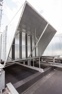
Fig. 0 baffle (splitter) silencer with rectangular cross section, with rain hood
Such noise reduction devices can, depending on the needs of each project, be installed to limit the transmission of acoustic power to the intake or discharge of a facility (e.g. Heating Ventilation Air Conditioning - HVAC -, industrial process) or even to limit it through the walls of a duct being a section of a network (the silencer then allows the limitation of the sound level downstream of it i.e. inside the duct whose walls - someytimes: thin - must attenuate the noise, which contributes - all things being equal -, to limit the sound level outside the duct) e.g. in the case where the section of network in question crosses a space in which control of the sound environment is appropriate (depending on the context: inside a building or outside).
The sizing of baffle (splitter) silencers - taking into account the input data appropriate for each application[0] - can be carried out, for quite a long time, using Module 1 of the SILDIS®[1] software, general information relating to the features of this simulation tool which is at the same time versatile, reliable, precise and user-friendly being available in other pages of this site[2][3], being completed and dealt in-depth in this article with regard specifically to the optimization of aeraulic (aerodynamic) and acoustic performance (variable with frequency), including notably for low frequency, according to a principle other than that of plate resonators with circular, square or slotted perforations, what is the subject of another post[4], and yet of another for the particular case of panels with millimetric or sub-millimetric perforations[5].
A first reason often leading an engineer or a technician (e.g. working in a design office, in an engineering structure related to the construction of buildings, hardware or machines) to look closely at the performance of a low frequency baffle silencer is linked to the richness, in the 1/1 octave bands of central frequency 125 Hz and 250 Hz (for air at room temperature) of the sound spectrum of equipment of which it is desirable to attenuate noise, due to the very high sound levels emitted in the absence of soundproofing devices, even taking into account the A-weighting (taking into account the sensitivity of the human ear) - even more as the discrete frequencies emissions are always undesirable[6] -). In practice, this is the case for numerous noise sources in relation to which baffle silencers must be considered, e.g. industrial fans (alone or integrated into refrigeration or thermal production equipment), compressors, generators, motors and combustion turbines.
A second reason is the frequency dependence of the sounproofing efficiency of a baffle (splitter) silencer. Because, in general, is increasing with the complement to 1 (100%) of the free passage rate[7] for the fluid - just like the singular pressure loss (total pressure loss) (at the inlet and at the outlet of the silencer), the latter increased by a linear pressure loss constituting a limiting factor for the sizing - the overall acoustic performance (insertion loss, transmission loss) which also depends on the service conditions (thermodynamic parameters), and as indicated previously, on the frequency:
- propagation loss Da.L (dB): - limited by the bypass paths of the sound waves e.g. longitudinally, for the walls of the silencer casing, which can be accounted for by a corrective term Dc (dB) - , it is proportional to the length L and it also depends on the acoustic behavior of the filling as resulting from the nature and thickness of the different layers:
- porous materials[8] i.e. internal part of the splitters (baffles core) e.g. mineral or polyester wool, open cell foam (in some cases, a surface covering, a perforated sheet can be modeled like this)
- surfacings[9] i.e. a covering layer e.g. anti-erosion glass veil (cloth) or fabric, membrane
- perforated protections[10] i.e. (when present), the most protruding layer in the airway
- reflection loss Dr (dB): linked to the change of cross section upstream and downstream of the splitters (baffles)
Of course, the combination of the different parameters mentioned previously has a more or less significant influence on these performance components which can vary in large proportions (for a given frequency, and with respect to adjacent frequencies):
- each considered separately: Da.L + Dc (dB), Dr (dB)
- in case of combination, for what concerns the insertion loss without consideration of the self-noise (flow noise) Di' = Da.L + Dc + Dr (dB)
But, taking into account the physical phenomena involved, the general appearance of the curves of the components of the acoustic performance of a silencer with baffles (splitters) as a function of frequency presents recurring similarities (with a logarithmic scale for the abscissa), such as illustrated by Figures 1 to 3 in relation to a concrete case of an silencer being ordinary (as to its constitution, its open area ratio, its operating conditions) intended for a ventilation installation (attention is drawn to the different scales used for graph ordinates):
- "dromedary's back" or "camel's back" (for a combination of input data other than the one basing the present figures) shaped curve for the propagation loss Da.L (dB) (see figure 1), and for the sum Da.L + Dc (dB) taking into account the shape of the bypass correction curve Dc (dB) (see figure 2)
- "S" shaped or "sigmoid" curve for the reflection loss Dr (dB)

Fig. 1 Propagation loss of a baffle (splitter) silencer depending on frequency

Fig. 2 By-pass correction of a baffle (splitter) silencer depending on frequency

Fig. 3 Reflection loss of a baffle (splitter) silencer depending on frequency
Thus, it follows from the above that the general appearance of the curve of the overall acoustic performance of a silencer with baffles (splitters) as a function of frequency presents recurring similarities (with a logarithmic scale for the abscissa), such as illustrated by Figure 4 in relation to the concrete case considered for Figures 1 to 3:
- "wobbly dromedary's back" or "wobbly camel's back" (for a combination of input data other than the one basing the present figures) shaped curve for the insertion loss without consideration of self-noise (flow noise) Di' = Da.L + Dk + Dr (dB)
- inbalance of the effectiveness of the noise attenuation device to the advantage of medium frequencies, to the detriment of high frequencies, and even more (due to almost zero reflection loss) to the detriment of low frequencies; here (see figure 5) Di' = 38.9 dB in the 1/3 octave frequency band centered on 1kHz while Di' = 9.1 dB in the 1/3 octave frequency band centered on 5000 Hz (upper frequency of the 1/1 octave band centered on 4kHz)[11], and while Di' = 3.5 dB in the 1/3 octave frequency band centered on 100 Hz (lower frequency of the 1/3 octave band 1/1 octave centered on 125 Hz)[11]

Fig. 4 Insertion loss of a baffle (splitter) silencer without consideration of self noise (flow noise) (curve)

Fig. 5 Insertion loss of a baffle (splitter) silencer without consideration of self noise (flow noise) (table)
The insertion loss without self noise (i.e. without noise due to the flow of the fluid) D'i (dB) considered previously can be subtracted from the sound power level without silencer Lw0 (dB ref. 1pW), and the result of this operation Lw1' (dB) can be combined - by means of a "logarithmic summation" - with the silencer self noise level i.e. the sound power level emitted by the flow of the fluid between the baffles (splitters) Lw (dB ref. 1pW) to obtain the sound power level with silencer Lw1 (dB ref. 1pW); the "dynamic" insertion loss i.e. the insertion loss taking into account the flow noise is then Di = Lw1 - Lw0 (dB) (cf. figures 6 et 7).
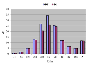
Fig. 6 Static and dynamic insertion loss of a baffles (splitter) silencer
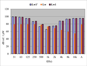
Fig. 7 Sound power level reduction by means of a baffle (splitter) silencer
The insertion loss of a baffle silencer taking into account the flow noise Di (dB) as mentioned previously (simulated with the SILDIS® software) is comparable to the measurement results according to the NF EN ISO 7235 Acoustics standard. - Laboratory measurement procedures for in-duct silencers and terminal units - Insertion loss, flow noise and total pressure loss. It therefore corresponds to the least attenuated mode, assuming a plane wave front, which is not always strictly the case for test benches and even less so in the conditions of installation of a baffle (splitter) silencer, from what it results that the acoustic performance for high frequencies can in practice be higher than that calculated (and this is agood thing indeed, with a view to obtaining on site foreseen and/or guaranteed results).
The challenges of sizing a baffle silencer are multiple, requiring compromises when factors are antagonistic:
- adaptability to the site and operating conditions, consideration of installation and maintenance constraints
- control of the cost which can be increased by larger dimensions (e.g. when trying to increase performance by extending the length and/or section of the silencer to compensate for the reduction in the passage rate) and/or the use of high cost raw materials and/or sophistication of construction
- aeraulic performance
- acoustic performance
With regard to this last challenge (which is not the least), it is always a question of selecting/developing a design with which efficiency over the entire frequency interval specific to each project[11] can be associated, even though the modification of numerous parameters of a silencer with baffles (splitters) e.g. properties and thickness of the layers, ratio of the thickness of the baffles (splitters) to the width of the air channels induce (even when only one parameter varies) contrary variations of acoustic performance for different frequencies to be considered. This is true for fixed operating conditions, and the task is even more difficult when variable operating regimes must be considered for some sophisticated industrial processes (e.g. with modification of the flow rate and/or of the temperature of the fluid in the silencer).
Considering what was expound, mastery of the design and calculations of baffle (spiltter) silencers with high insertion loss in an extended frequency domain - i.e. with a broadband sound attenuating device, including the 1/1 octave central frequency bands 125 Hz and 250 Hz (for air at ambient temperature or - this is even more difficult - for another fluid, sometimes at high temperature) - often determines the feasibility of a high performance baffle silencer, as required for many applications in the construction sector (HVAC hardware e.g. with fans) or for industrial applications (e.g. in relation to the production of energy, the compression of fluids, the evacuation of burnt gases).
SILDIS® software allows the design and sizing calculations of high-performance baffle (splitter) silencers for various applications (e.g. for air conditioning or ventilation networks, for air intakes, exhaust lines of engines and combustion turbines, process chimney ducts) with a sophistication of modeling resulting from Research and Development (R&D) work carried out by ITS human resource for decades, particularly in terms of multilayered acoustic structures properties and of sound propagation in ducts and in sound absorbing media.
Taking into account a median symmetry plane, a half baffle (splitter) can be taken into account - with SILDIS® software - in the form of a multi-layer acoustic structure, the number of sub-assemblies of which (each with a porous medium[8], possibly covered on the one hand with a surfacing[9] and on the other hand with a perforated protection[10]) is variable (from 1 to 4) depending on the considered assembly (cf. fig. 8)

Figure 8 Multilayer acoustic structure (i.e. combination of materials) considered for predicting the acoustic performance of silencers with Module 1 of the SILDIS® software - C, G, K, O: porous medium[8] - D, H, L, P: surfacing[9] - E, I, M, Q: perforated protection[10] |
The functional calculation diagram for predicting the acoustic performance of silencers with Module 1 of the SILDIS® software is as illustrated in Figure 9 in the case of a filling made of a sound absorbing material being locally reacting[12].

Figure 9 Functional calculation diagram for predicting the acoustic performance of silencers with Module 1 of the SILDIS® software in the case of a filling made of a sound absorbing material being locally reacting[12] |
In the case of a bulk reacting absorber, the functional diagram is slightly modified for the calculation steps upstream of step [F] (a function depending on the properties of the lining and on the geometry of the silencer being substituted for the surface impedance), but the calculations are much more complicated, a fortiori when anisotropy - variation in the properties of the porous medium constituting the baffles (splitters) core depending on the direction - is taken into account. Whatever the hypothesis of sound propagation considered (filling locally reacting[12], or bulk reacting - isotropic or anisotropic -), those calculation steps upstream of step [F] are crucial for calculating the acoustic performance of baffles (splitter) silencers.
In this regard, it is important to keep in mind that knowing that a silencer lining is based on wool with a density of 45 kg/m3 provides little more information about its acoustic properties than knowing that a candy weighs 100 grams provides information on its gustatory qualities.
There is no reliability or precision for the calculations of step [F] and for subsequent (steps [G] to [K]) without robust modeling of the behavior of the considered acoustic structure, which is achieved by means of the COALA (COmputation of Acoustic LAyers) routine which constitutes a common core for several modules of the SILDIS® software and only requires knowledge of basic materials data (as measurable in a laboratory e.g. using a standing wave apparatus i.e. a Kundt's tube).
The reliability of such measurements is decisive for a sufficiently precise determination of intermediate quantities (compressibility modulus, effective density, characteristic impedance, wave number) over the entire frequency range of interest (this is an arduous task, even with the most sophisticated models):
- independently of the quality of the measurements strictly speaking, the representativeness of the samples tested sometimes raises questions (having to take into account, for a given commercial name, the variability of manufacturing at a given time period, changes in manufacturing over time e.g. when new health regulations lead to significant changes in the size of the fibers of certain porous materials and/or when the characteristics of certain adjuvants are modified)
- the durability and maintenance over time (after the silencer has been put into service, and it has undergone aging) of the characteristics of the materials taken into account at the time of sizing are subject to uncertainties, particularly in the event of contexts of unfavorable use (e.g. fluids with aggressive physicochemical properties, high temperature)
This said, the functionalities of module 1 of the SILDIS® software are particularly suitable for carrying out parametric studies of the acoustic performance of baffle (splitter) silencers, to quantify the impact of numerous factors:
- influence of sound-absorbing filling flow resistivity
- influence of sound-absorbing filling anisotropy effect of a laminated sound-absorbing filling (each porous layer being with different properties e.g. flow resistivity or other parameters)
- effect of a cloth (e.g. fabric, unwoven)
- effect of a perforated protection (e.g. perforated sheet with circular holes and square or hexagonal array, or with square holes, and also: slotted superficial layer)
- effect of temperature
- effect of pressure
- effects of fluid flow velocity
Besides, they allow the evaluation of aeraulics (aerodynamic) performance):
- influence of various geometries for the splitters/the sound-absorbing lining for both upstream and downstream e.g. extremity with rectangular, semi-circular shape (or even more aerodynamically profiled: downstream only).
Acoustical performance of baffle (splitter) silencers with unique (symmetrical) sound absorbing filling (lining)
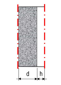
Baffle silencers with unique (symmetrical) sound-absorbing filling (lining) are those for which, when it comes to acoustic performance simulations with plane waves (for the least attenuated mode), the calculations can relate to a sub-set as illustrated in Figure 10 (which is a schematic cross section), on which the planes of symmetry are shown in red.
|
Figure 10 Cross section of a sub-set of a baffle (splitter) silencer with a unique (symmetrical) sound absorbing filling (lining) ; symmetry planes are shown in red |
- acoustical structure
on each side of an air channel (2h wide), the sound-absorbing fillings (linings) which constitute the baffles (splitters) both have the same half-thickness (d) and the same constitution (i.e. the same stack of layers of sound-absorbing materials); all or part of the multilayer acoustic structure of Figure 1 is possibly taken into account with, depending on the case, porous media[8], surfacings[9] perforated protections[10] - sound propagation
it is possible to consider one of the following sound propagation hypothesis:- absorber locally reacting[12]
- isotropic absorber i.e. with identical properties along longitudinal axis (x) and transverse axis (y)[13] for porous materials
- anisotropic absorber i.e. with different properties along longitudinal axis (x) and transverse axis (y)[13] for the porous medium of set 1
- fluid (gas) speed
fluid (gas) speed is accounted:- for the calculation of propagation loss (depending on value and direction)
- for the determination of silencer self noise (flow noise)
Acoustical of baffle (splitter) silencers with alternate i.e. dissimilar (unsymmetrical) filling (lining)
Baffle (splitter) silencers with alternate i.e. dissimilar (unsymmetrical) sound absorbing filling (lining) are those for which, when it comes to acoustic performance simulations with plane waves (for the least attenuated mode), the calculations can relate to a sub-set as illustrated in Figure 11 (which is a schematic cross section), on which the planes of symmetry are shown in red
|
Figure 11 Cross section of a sub-set of a baffle (splitter) silencer with alternate i.e. dissimilar (unsymmetrical) sound absorbing filling (lining) ; symmetry planes are shown in red |
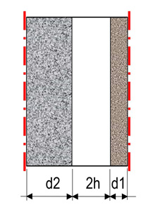
- acoustical structure
on each side of an air channel (2h wide), the sound-absorbing fillings (linings) which constitute the baffles (splitters) do not have the same half-thickness (one distinguishes between d1 and d2) and/or the same constitution (i.e. they do not have the same stack of layers of sound-absorbing materials)-
for one, set 1 is accounted i.e. layers CDE of figure 8 depending on the case 1 porous mediuam[8], 1 surfacing[9], 1 perforated protection[10]
-
for the other, set 2 is accounted i.e. layers GHI of figure 8 depending on the case 1 porous mediuam[8], 1 surfacing[9], 1 perforated protection[10]
-
- sound propagation
it is possible to consider one of the following sound propagation hypothesis:- absorber locally reacting[12]
- asotropic absorber i.e. with identical properties along axis x and y[13] for porous media
- fluid (gas) speed
fluid (gas) speed is accounted:- for the determination of silencer self noise (flow noise)
Optimization of the performances of baffle (splitter) silencers with respect to their sound absorbing filling (lining)
The optimization of the performance of baffle (splitter) silencers with respect to their sound-absorbing filling (lining) concerns first and foremost the propagation loss Da.L (dB), for different reasons:
- except in the case of ultra-short silencers, it is among the terms Da.L, Dc, Dr of the sum Di' = Da.L + Dc + Dr (dB) mentioned above regarding the insertion loss without consideration of the self-noise (flow noise) which is the most significant in numerical value
- the corrective term Dc (dB) is linked to it and its importance can be put into perspective:
- taking into account the difference between the theoretical value Da.L (dB) and the measurement result, it therefore depends on the choices made at different stages of the modeling allowing the evaluation of Da.L (dB); it is therefore not strictly usable in the event of different choices (which is sometimes required)
- measured (in general: in a laboratory, therefore at ordinary temperature and pressure -) it cannot be rigorously extrapolated for different service conditions (e.g. with a fluid other than air, a fortiori at high temperature) and it is different depending on the characteristics of the ducts in terms of nature (e.g. concrete, metallic) and thickness (often variables) considered on the one hand for the measurements and on the other hand for the case studied
- the reflection loss Dr (dB) is linked to several parameters basing it also (according to some theoretical models), or otherwise very low in numerical value (when it is assumed to be based only on geometric criteria - except in the case of pass rate values[7] very small, which are generally not used in practice because they compromise the aeraulic performance of the silencer -) and its importance can be put into perspective:
- when based on measurements, it cannot be rigorously extrapolated for different service conditions (e.g. with a fluid other than air, especially at high temperature)
- it sometimes (often?) takes into account the imperfection of the test bench in which measurements were carried out when the condition of plane sound waves is only imperfectly respected, whereas one is interested (which is usual) in the least attenuated mode (the reflection loss resulting from such measurements is then, sometimes, unduly greater than that corresponding to the propagation of plane waves)
One of the advantages of the consideration of the terms Dc and Dr (both in dB) by the SILDIS® software is to make possible comparisons of the simulated insertion loss Di (dB) of baffle (splitter) sielncers with publications - scientific or commercial e.g. provided by sound attenuators manufacturers - based on measurement results (e.g. based on the standard NF EN ISO 7235 Acoustics - Laboratory measurement procedures for ducted silencers and air terminal units - Insertion loss, flow noise and total pressure loss).
A stength of the SILDIS® software is to be able to combine (for a fluid with variable thermodynamic conditions, including high temperature, and even if it is not air) the consideration of the various effects relating to the acoustic structure, to the conditions of sound propagation and to the fluid (gas) speed, in a sufficiently complete and robust manner and to allow, depending on the length, optimization of the performance of baffle silencers, at a given frequency:
- for unique (symmetrical) sound-absorbing filling (lining)
regarding acoustics, with respect to the porous material(s) (i.e. the core of the baffles):- with preponderance of the ratio 2d/2h of the thickness of the baffles (2d) to the width of the air passages (2h) and the relative resistance to the passage of air r[14]; with the ability to consider laminated filling (lining)
- with the capability to modify the performance (or to take into account the modification of performance if it is imposed elsewhere) when adding a surfacing (cloth, fabric but also membrane) and/or perforated protection (sheet metal with uniform holes - possibly with micro-perforations - but also plate with slits)[2][4][5]
- taking into account all possible (usual) behaviors for the absorber: locally reacting[12] or bulk reacting (isotropic, anisotropic)
regarding acoustics, with respect to fluid (gas) speed:
- taking into account its influence as completely as possible i.e. on the one hand in terms of propagation loss (value and direction in relation to the direction of sound propagation) and on the other hand with regard to soundproofing device self noise (flow noise)
regarding aeraulics (aerodynamics):
- with preponderance of the ratio 2h/2d of the width of the airways (2h) to the thickness of the baffles (2d); taking into account the roughness of the sound-absorbing lining and with the capability of consideration of rounded or profiled ends to limit the total pressure loss (pressure drop)
overall, with a fairly large freedom for silencers sizing for the acoustical engineer or technician, to adapt to various requirements with possibilities offered by the SILDIS® software - particularly in the case of parametric studies and case studies - as provided in another page of this site[3]
- for alternate i.e. dissimilar (asymmetrical) sound-absorbing fillings (linings)
regarding acoustics, with respect to porous material(s) (i.e. the core of the baffles - splitters -):-
with preponderance of the ratios 2d1/2h and 2d2/h of the thickness of the baffles - splitters (2d1 and 2d2) to the width of the air passages (2h) and the relative resistances to the passage of air r1[15] and r2[16]
-
with the capacity to modify the performance (or to take into account the modification of performance if it is imposed elsewhere) when adding a surfacing (cloth, fabric but also membrane) and/or perforated protection (sheet metal with uniform holes - possibly with micro-perforations - but also plate with slits)[2][4][5] which may not be identical for the two sound-absorbing surfaces facing each other (set 1 and set 2)
- taking into account 2 possible (usual) behaviors for the absorber: locally reacting[12] or bulk reacting (isotropic)
regarding acoustics, with respect to fluid (gas) speed:- (due to the complexity of the calculations, at least provisionally) without taking into account its influence on the propagation loss, but taking it into account for the self noise (flow noise) of the soundproofing device
regarding aeraulics (aerodynamics):- with preponderance of the ratio 2h/(d1+d2) of the width of the airways (2h) to the sum of the half-thickness of the baffles (d1 and d2); taking into account the roughness of the sound-absorbing lining and with the capaility of considering rounded or profiled ends to limit the total pressure loss (pressure drop)
(pending eventual further developments of SILDIS® software) overall, for applications for which the Mach number is sufficiently small (compared to 1) so that the effect of the fluid (gas) speed can be neglected for some steps of the calculations as presently (temporaily ?) implemented, with even greater freedom for sizing for the engineer or acoustic technician, to adapt to various requirements, since the possible combinations of key factors are multiplied- this includes already, in practice, many contexts e.g. for air at conditions close to ambient conditions (the Mach number is close to 0.058 for air at a pressure of 1 bar, at a temperature of 20 °C ): Heating Ventilation Air Conditioning - HVAC installations, air intake and discharge of compressors, air intake of engines, gas turbines and other processes involving combustion
with possibilities offered by the SILDIS® software complementing those offered fo silencers with unique (symmetrical, conventionnal) filling, namely as illustrated below -
Special cases of design and calculations of high performance baffle (splitter) silencers based on alternative principles
Of course, the SILDIS® software allows parametric studies of baffle (splitter) silencers such as are usually available on the market, including for combinations of dimensions and packing not covered by laboratory tests, and also for different service conditions (e.g. at higher temperature, with a different fluid, with a higher airway speed). But that's not all: different special cases of design and calculations of baffle (splitter) silencers based on alternative principles can be mentioned to illustrate the power of the SILDIS® software and the valuable help it can provide in the context of engineering or Research and Development (R&D) works in acoustics (building, industry, environment).
In the following, special cases of design and calculations of baffle (splitter) silencers (with a rectangular cross section) are presented - with performance comparisons - for, instead of the ordinary unique sound absorbing lining (R assembly), alternate sound absorbing linings (RA' assembly with thickness variation, RA'' assembly with constitution variation, RA''' assembly with constitution variation and with a single thickness). Figures 12 to 15 below show a schematic longitudinal section (not taking into account possible variations in the shape of the ends of the baffles at the inlet and outlet of the silencers) of each of the aforementioned assemblies for the same number of airways (2h constant in all cases).
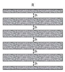
Figure 12 Silencer with symmetrical baffle (splitter) arrangement |
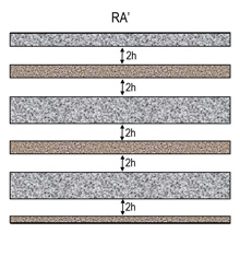
Figure 13 Silencer with unsymmetrical baffle (splitter) arrangement, with thickness variation |
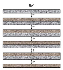
Figure 14 Silencer with unsymmetrical baffle (splitter) arrangement, with constitution variation |
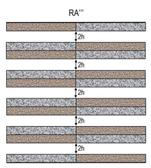
Figure 15 Silencer with unsymmetrical baffle (splitter) arrangement, with constitution variation, but with unique thickness |
- for limiting pressure loss
there are other ways to reduce the total pressure loss than increasing the frontal section of the silencer (which requires more space and is expensive) and/or playing on the upstream and/or downstream geometry of the splitters (baffles), of which length should also be limited
a 2d thickness of sound-absorbing material, chosen sufficiently large to allow low frequency absorption, is often likely, if it is applied to all the splitters (baffles), to cause an undesirable reduction in the open area ratio (should one recall ? leading to an increase in the section of the silencer and/or an increase in the pressure loss) while it is not always necessary that all the sound absorbing surfaces facing each other are as thick (the alternation of thickness 2d and 2d.x with x<1, can - in some contexts - not significantly reduce the acoustic performance (propagation loss) while significantly increasing the aeraulic performance (much lower total pressure loss)
It is possible using SILDIS® software to predict the noise attenuation and aerodynamic performance of such silencers.
Figures 16 (fine band results) and 17 (results per 1/1 octave band) below present the propagation loss simulated with the SILDIS® software for a length of 1 m of two baffle (spiltter) silencers, both with the same airway width 2h:
- one according to the assembly R of Figure 12 i.e. with a unique sound-absorbing lining (as ordinarily used - to date - by manufacturers of noise attenuation devices for air networks of Heating Ventilation Air Conditioning - HVAC - facilities)
- the other according to the RA' assembly of Figure 13 i.e. with alternate sound-absorbing lining with variation in the thickness of the baffles (half with a thickness 2d and half with a thickness 2d.x with x<1)
It can be observed that the difference in terms of propagation loss for the RA' assembly (alternate sound-absorbing lining with thickness variation), when it is unfavorable (which is not the case at all frequencies), does not exceed 1.1 dB over the entire frequency spectrum (i.e. for the 1/1 octave bands of central frequency 31 Hz to 16 kHz) while the calculations show for these configurations a reduction in the total pressure loss (pressure drop) of 18% to the advantage of the RA' assembly (with a simultaneous reduction in the frontal section of the silencer by 9 % to the advantage of the RA' assembly).
Of course, different combinations of parameters impacting the propagation loss of baffle (splitter) silencers can lead for such comparisons of performance indicators to different results for each specific case (the reduction in the total pressure loss at the advantage of the RA' assembly can be much greater in some cases). In relation to such simulations - in their whole - as they were carried out at ITS in the context of Research and Development - R&D work - the following can be mentioned, with regard to the RA' assembly (alternate sound-absorbing filling with thickness variation), on the condition of a judicious choice of some parameters (this is a kspecific now-how, which the time spent on such calculations allows to improve):
- acoustic performance can be maintained almost at the level of R assembly (unique sound-absorbing lining)
- the aeraulic (aerodynamic) performance can be significantly improved compared to that of the R assembly (unique sound-absorbing lining)
- the footprint can be significantly reduced compared to that of the R assembly (unique sound-absorbing lining), due to the reduction of the frontal section
- (consequently, this aspect of the comparison, beyond technical considerations, should not be neglected) the manufacturing cost can be significantly reduced compared to that of the R assembly (unique sound-absorbing lining), due to the reduction, at the same time:
- of the volume of the sound-absorbing filling
- of baffle (spiltters) frames
- of wall areas of casing
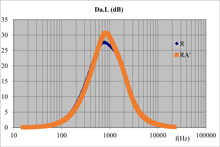
Figure 16 Compared acoustical performance of baffle (splitter) silencers with unique or alternate filling: thickness influence |
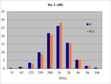
Figure 17 Compared acoustical performance (per octave band) of baffle (splitter) silencers with unique or alternate filling: thickness influence |
- for increasing low frequency performance
In many contexts, for a given airway width 2h - which conditions (for a given frontal section) the speed of passage of the fluid between the splitters (baffles) and therefore not only the self noise of the silencer, but also the choice of anti-erosion superficial linings and the total pressure loss at the inlet and outlet -, and for a given length (considering the noise attenuation devices most commonly marketed by manufacturers) :
- the low frequency performance is lower than that required (increasing disproportionately- and this is not always enough - the length of the baffles often presents technical disadvantages - increase in the linear total pressure loss, increase in footprint and in fabrication cost -)
- mid-frequency performance is (unnecessarily) significantly higher than required
Then, it is possible, thanks to the powerfull acoustic and aeraulic simulation tool that Module 1 of the SILDIS® software is, to modify the design of the construction and the arrangement of the baffles (spiltters) to overcome this drawback by improving the balance of acoustic performance in frequency.
Figures 18 (single frequency results) and 19 (results per 1/1 octave band) below present the propagation loss simulated with the SILDIS® software for a length of 1 m) of two silencers with baffles (splitters) of the same thickness, and having the same width of the airways 2h:
- one according to assembly R of Figure 12 i.e. with a single sound-absorbing lining (as ordinarily used - to date - by manufacturers of noise attenuation devices for air networks of Heating Ventilation Air Conditioning - HVAC - facilities)
- the other according to the assembly RA'' of Figure 14 i.e. with an alternate sound-absorbing lining with variation in the constituion of the baffles (half with an ordinary surfacing and half with a modified surfacing); since the total thickness of the baffles is unique, the performance of this RA'' assembly is equivalent to that of the RA''' assembly (which may be of practical interest with regard to the fabrication of the silencer elements/thir stability)
It can be observed that the propagation loss in the 1/1 octave frequency band centered on 125 Hz is, for the RA''/RA''' assembly (alternate sound-absorbing filling with variation of the constitution), more double (7.3 dB/m versus 3.6 dB/m, what is considerable) of that of the R assembly (single sound-absorbing lining), without notable alteration of performance in the 1/1 octave bands centered on 31 Hz, 63 Hz, 250 Hz; the reduction in performance of the RA''/RA''' assembly compared to the R assembly only concerns frequencies above 500 Hz for which the propagation loss (at least in the frequency zone corresponding to the highest performance) is often greater than that required (a propagation loss greater than 15 dB/m in the 1/1 octave band centered on 500 Hz, and greater than 10 dB/m in the 1/1 octave band centered on 1 kHz - as this is the case for the RA assembly'' in the example considered - is often sufficient in practice). Coming back to the performance in the octave band centered on 125 Hz as for above example, if it were to be considered alone - which is improbable in practice - it follows from what has been explained previously that when using the RA''/RA''' assembly (alternate sound-absorbing filling with variation in constitution), that the length of the silencer could be reduced by half (which is, again, considerable) compared to that required with the R assembly (ordinary unique sound-absorbing filling).
Of course, different combinations of parameters impacting the propagation loss of baffle silencers can lead for such comparisons of performance indicators to different results for each specific case (the variation of the propagation loss in frequency at the advantage of the RA''/RA''' assembly can be even more important in some cases). In relation to such simulations - in their whole - as they were carried out at ITS in the context of Research and Development - R&D work - the following can be mentioned, with regard to the RA''/RA' assembly '' (alternate sound-absorbing filling with variation of the constitution), on the condition of a judicious choice of some parameters (this is a specific know-how, which the time spent on such calculations makes it possible to improve):
- the acoustic performance can be significantly increased in the 1/1 octave frequency band centered on 125 Hz and/or 250 Hz, e.g. by the use of a modified surfacing for half of the surfaces in contact with the fluid (but also by varying the nature of the wool constituting the core of the baffles), while being kept almost at the level of that of the R assembly (single sound-absorbing lining) for lower frequencies; the reduction in performance of the RA''/RA''' assembly compared to the R assembly can only concerns frequencies above 500 Hz for which the propagation loss (at least in the frequency zone corresponding to the highest performance) is often higher than that required
- the aeraulic (aerodynamic) performance is not reduced compared to that of the R assembly (single sound-absorbing lining)
- the footprint can be significantly reduced compared to that of the R assembly (single sound-absorbing lining), by reducing the length of silencer necessary to obtain a given performance (in the 1/1 octave band centered on 125 Hz/250Hz)
- (consequently, this aspect of the comparison, beyond technical considerations should not be neglected) the fabrication cost can be - even when one accounts a modification of the surfacing - globally reduced compared to that of the R assembly (single sound absorbing padding), due to the reduction, while at a time:
- of the volume of the sound-absorbing filling
- of baffle frames
- of the wall areas of the silencer casing
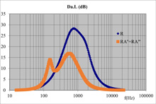
Figure 18 Compared acoustical performance of baffle (splitter) silencers with unique or alternate filling: constitution influence |
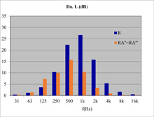
Figure 19 Compared acoustical performance (per octave band) of baffle (splitter) silencers with unique or alternate filling: constitution influence |
Globally, concerning design and calculations of high performance baffle (splitter) silencers
When developing high-performance baffle silencer devices, design and calculations - of course - play a key role:
- baffles (splitters) being identical do not always constitute the acme
- laboratory tests of a necessarily limited number of combinations of geometries and sound-absorbing linings, necessarily at ambient temperature, and for low passage speeds of air - and not of another fluid - is not not the unsurpassable horizon to characterize their effectiveness
ITS offers another approach (complementary) for sizing high-performance baffle (splitter) silencers, based on numerical simulations opening up the field of possibilities.
Software engineering and publishing at ITS are activities covered by ISO 9001 certification with regard to quality management[18]; they are oriented towards the development of solutions combining reliability and durability in various soundproofing contexts, including when high technicality is required.
Module 1 of SILDIS® software (the present stage of development results from several thousand hours of research and programming by a human resource experienced in physics) allows the design and calculations of baffle (splitter) silencers either conventionnal or based on alternative principles, making possible fabrication other than that - common for most manufacturers, more or less artisanal or industrial - based on splitters (baffles) that are all identical, with wool filling selected once and for all a long time ago (when it is not polyester: with anti-erosion protection - selected a long time ago -, or even with perforated sheet metal) which does not always constitute - far from it - the ultimate.
Compared to the R assembly (single sound-absorbing lining, illustrated by Figures 10 and 12 above), - with an appropriate selection of different parameters impacting acoustic and aeraulic (aerodynamic) performance - :
- the RA' assembly (alternate sound-absorbing lining, with variation in thickness illustrated by Figures 11 and 13 above) can allow - with an appropriate selection of different parameters impacting acoustic and aeraulic (aerodynamic) performance - an increased overall competitiveness of baffles (splitter) silencers in many contexts where the aeraulic (aerodynamic) performance, the footprint of the silencer as for its cross section, and its price -for a given acoustic performance more or less kept - are key factors
- the RA''/RA''' assemblies (alternate sound-absorbing lining, with variation in constitution illustrated by Figures 11, 14 and 15 above) can allow increased overall competitiveness of baffle (spilter) silencers in many contexts where the acoustic performance at low frequency e.g. in the 1/1 octave band centered on 250 Hz, the footprint of the silencer as for its length and its price - for a given aeraulic (aerodynamic) performance, rigorously preserved or even improved over the length of the silencer is reduced - are key factors
The future will tell whether such concepts of unconventional soun attenuators, for which the prediction of the acoustic and aeraulic performance is possible with the SILDIS® software (and could possibly be the subject of continuous improvement actions which underpin the very existence of ITS to allow even more innovations ?), constitute means of solving a specific problem which would be posed in terms of sizing in the context of a specific project or if they will be a game-changer and will contribute to the development of new standards in terms of baffle (spilitter) silencers.
[0] cf.
[0] cf. What are the input data useful for the design of a silencer ?
[1] Sound Impact Limitation Design for Industrial Solutions https://www.its-acoustique.fr/en/acoustical-insulation-soundproofing/acoustic-aeraulic-construction-cad-calculation-software.html
[3] cf. Prediction of acoustic and aerodynamic performance of silencers - software SILDIS® Module 1
[6] for example, French regulations relating to environmental noise consider their existence when, for an unweighted third-octave spectrum due to the operation of a noisy facility, the level in a frequency band exceeds by 10 dB that of the two adjacent frequency bands from 63 to 315 Hz (by 5 dB or more the average level of the two adjacent frequency bands from 400 Hz to 6300 Hz)
[7] ratio of the fluid passage area to the frontal area (taking into account the cumulative thickness of the absorbent filling layers)
[8] characteristics taken into account: resistivity, porosity, tortuosity, thermal characteristic length, viscous characteristic length, density, thickness
[9] characteristics taken into account: airflow resistance, mass density, thickness
[10] characteristics taken into account: porosity, perforation geometry, mass density, thickness
[11] in many contexts, the frequency interval corresponding to the octaves of central frequency 125 Hz to 4 kHz is of greater interest in the building sector, that corresponding to the octaves of central frequency 63 Hz to 8 kHz or even 16 kHz should be considered for many industrial projects
[12] a local reaction means an absence of longitudinal sound propagation (i.e. no sound propagation in absorber in the flow direction) is assumed, whether it results from a sufficiently large resistance to the passage of air of the packing material, or from transverse partitions provided for purpose
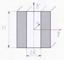
[13] location of the x, y and z axes for calculations of the acoustic performance of baffle (splitter) silencers
|
Figure 7 Sound propagation in a baffle (splitter) silencer |
[14] r = σ * d / Z0 with σ flow-resistivity of unique porous medium (Nsm-4), d half-thickness of unique porous medium (m), Z0 charactéristic impedance of fluid (gas) (Nsm-3) - for a non-laminated filling (lining) -
[15] r1 = σ1* d1 / Z0 with σ flow-resistivity of porous medium of set 1 (Nsm-4), d1 half-thickness of porous medium of set 2 (m), Z0 charactéristic impedance of fluid (gas) (Nsm-3) - for a non-laminated filling (lining) -
[16] r2 = σ2* d2 / Z0 with σ flow-resistivity of porous medium of set 2 (Nsm-4), d2 half-thickness of porous medium of set 2 (m), Z0 charactéristic impedance of fluid (gas) (Nsm-3) - for a non-laminated filling (lining) -
[17] the propagation loss Da.L displayed for the silencer length L considered is less than the insertion loss Di', as ordinarily measurable in practice e.g. because the latter takes into account the reflection loss Dr which can also be calculated with the SILDIS® software, and then added (modifying the displays in particular at the medium and treble frequencies)
[18] cf. Quality management