In the soundproofing sector, the selection (from a range of standardized products) or the development (custom-made) of silencers is a recurring engineering task in various contexts, the acoustic and aeraulic (aerodynamic) performance of such noise reduction devices being both multifactorial and antagonistic. In this field, experience then plays - of course - an important role, and appropriate tools determine the best technological choices.
The combination of geometric parameters e.g. thickness and spacing of the sound-absorbing lining, length of the silencer - what is referred to in this article as "macro-geometry" - is of major importance for the dimensioning of dissipative silencers (i.e. with sound-absorbing lining), impacting at the same time:
- the size of the considered noise attenuation device (which must take into account the installation context)
- the manufacturing cost (linked to the volume of the sound-absorbing lining, the dimensions of its frames, the surfaces of the walls of the silencer casing)
- the aeraulic (aerodynamic) performance which also depends on the upstream and downstream geometry of the elements of the sound-absorbing lining and of course on the service conditions (density and passage speed of the fluid)
- the acoustic performance
This last aspect (which is not the least when it comes to boosting the performance of silencers from a competitive advantage perspective) is a function of a large number of other factors than macro-geometry (listed on another page of this site[0]), the level of consideration of which is - in practice - quite variable depending on the context, considering:
- the (real or supposed) importance of the acoustic performance compared to the 3 other aspects mentioned above (with the possible preeminence - whatever the reasons - of the dimensions, the price, the total pressure loss - or 2 or 3 of these aspects -, the level of criticality of the control of noise levels, and the issues in the event of exceeding the admissible noise levels for the installation concerned)
- the knowledge of the human resource involved in the selection/development of the soundproofing concerned device (more or less specialized, more or less experienced, more or less open to alternative approaches: engineers or technicians from design offices, architects, personnel assigned to Research and Development - R & D -)
- the time allocated to accomplish the tasks related to the sizing of a silencer
- the means available for the calculations/selection of soundproofing equipment meeting - as far as is desirable - the requirements to be accounted for each project
Module 1 of the SILDIS® software is dedicated to predicting the acoustic and aeraulic (aerodynamic) performance of silencers (with a section being either rectangular i.e. with baffles/splitters or circular with or without central pod) for applications in the construction sector (e.g. Heating Ventilation Air Conditioning - HVAC - facilties) as well as in industry, or for environmental protection (ventilation of technical rooms and enclosures, air intake and discharges/exhausts of engines, turbomachines and various processes).
.jpg) Figure 1: silencer with rectangular cross section (front view) and silencer with circular cross section (side view) in an air network of a Heating Ventilation Air Conditioning (HVAC) facility |
It differs from tools (also called software) usually made available by manufacturers to enable the selection of a noise attenuation device among a range of products whose performance has been integrated into a fixed database, built from a limited number of measurements (for a fluid which is none other than air, at laboratory temperature and pressure conditions, with low-speed flow) and numerous interpolations and extrapolations (when it comes to meeting varied needs in terms of macro-geometries).
Such software packages display for a given macro-geometry of a silencer the insertion loss resulting from the restitution (with possible adjustments) of a value known in advance and stored; but neither the nature of the absorbent lining nor the thermodynamic conditions of the transported fluid and even less its speed and direction of circulation compared to that of sound propagation are variables for such a determination (the maintenance over the long term of the characteristics assumed for mineral fibre-based materials for which regulatory developments in terms of health risks have required manufacturers to significantly increase the diameter of the fibres - when they are measured in microns - raises questions with regard to the sustainability of the attenuation credited, at a given time, to some silencers).
The SILDIS® softwareS[1] (for which information relating to its scientific background and functionalities can be found in other pages of this site[2][3][4][5][6] is of a different nature, being - fundamentally - based on the resolution of the equations of sound propagation on the one hand in the air passages of the silencer, and on the other hand in its lining to allow the evaluation of the propagation loss Da.L (dB) for a silencer of any length L (m).
Considering a median plane of symmetry, a half-baffle of a silencer with a rectangular section (or the central pod of a silencer with a circular section, or even its peripheral sound-absorbing lining) can be taken into account - with the SILDIS® software - in the form of a stack of sub-assemblies (each with a porous medium[7], possibly covered on the one hand with a surfacing[8] and on the other hand with a perforated protection[9]) in variable quantity (from 1 to 4) depending on the assembly considered (see fig. 2).

Figure 2 Multilayer acoustic structure (i.e. combination of materials) considered for the prediction of acoustic performance of silencers with Module 1 of the SILDIS® software - C, G, K, O: porous medium[7] - D, H, L, P: surfacing[8] - E, I, M, Q: perforated protection[9] |
The functional calculation scheme for the prediction of the acoustic performance of silencers with Module 1 of the SILDIS® software is as illustrated in Figure 3 for the case of a locally reacting absorbing packing material (i.e. assuming that there is no sound transmission inside the absorber along the flow direction, either due to a sufficiently high resistivity or due to the installation of transverse partitions); this is not the only propagation condition that can be considered for the calculations, since the consideration of a homogeneous or anisotropic absorber is also possible with the SILDIS® software.

Figure 3 Functional calculation diagram for predicting the acoustic performance of silencers with Module 1 of the SILDIS® software in the case of a filling made of a sound absorbing material being locally reacting |
Indeed, in addition to the thickness and spacing of the sound-absorbing lining elements, and to length of the silencer (i.e. the macro-geometry of the silencer as defined above, without any particular dimensional limitation), the nature of the sound absorbing filling, the thermodynamic conditions of the fluid transported, its speed and its direction of circulation relative to that of sound propagation are taken into account for the calculations with the SILDIS® software, as required.
Correction terms are introduced for the reflection loss Dr (dB), and for a by-pass correction Dc (dB), in particular to allow the comparison of the results of simulations of the insertion loss of a dissipative silencer Di' = Da.L + Dc + Dr (dB) obtained with the software with the standardized measurement (with its imperfections, whatever the laboratory) e.g. according to the ISO 7235 standard Acoustics - Laboratory measurement procedures for duct silencers and terminal units - Insertion loss, flow noise and total pressure loss:
- which is theoretically (what about practice?) based on plane waves (there is a general consensus that this corresponds to the least attenuated mode)
- which depends on the sound reduction index of the duct walls, which is not necessarily always transposable to all practical cases (it is not the same thing to have a very thick masonry envelope as is found for example in the air inlet and outlet ducts of technical rooms e.g. rooms for generator sets or metal ducts constructed with a simple thin sheet as in ordinary air conditioning networks, and it cannot be expected that an acoustic performance undifferentiated in such contexts - for the same combination of baffle thickness, spacing and length, a fortiori if greater than 1 m - will be precisely evaluated)
- which, beyond the cut-off frequency of the duct, depends on the transverse dimensions of the air network (because they themselves play a role in the acoustic performance), and on the modal composition of the noise source, which is completely unknown in practice
This is why the issues relating to silencer insertion loss should always be considered with humility, and this is why one should not expect from the confrontation between prediction and measurements more than one can reasonably anticipate, when one knows the scientific and technical background of the required dimensioning calculations.
In such a context, the propagation loss Da.L (dB) and associated quantities expressed per unit of length (dB/m) i.e. Da for a length of 1 m, or even Da for a length corresponding to the width of the airways or Da for a length corresponding to the wavelength for the considered frequency, are the performance indicators (for which the conversion from one to the other is easy) whose determination suffers the least from uncertainties, and which allow objectively meaningful comparisons between different silencer configurations, for the purposes of optimizing acoustic performance.
For this, the use of SILDIS® software is very useful, and allows to boost the performance of silencers in different ways.
How to boost silencer performance with SILDIS® software by optimizing the packing, for a combination of geometric parameters e.g. thickness and spacing of the sound absorbing lining, silencer length (macro-geometry) being fixed
A way to boost silencer performance with SILDIS® software, for a combination of geometric parameters e.g. thickness and spacing of the sound absorbing lining, silencer length (macro-geometry) being fixed, is to optimize the lining i.e. to purposefully choose the characteristics of the multi-layer sound absorbing acoustic structure to increase the noise reduction associated with the implementation of such soundproofing equipment.
For a given macro-geometry (as defined above), the noise attenuation (in terms of propagation loss, with the variations mentioned above for the performance indicators expressed in dB/m) depends, for a given frequency, on the nature of the filling, that is to say both the thickness and the characteristics of the different layers of the acoustic structure illustrated in Figure 2.
In this context, the SILDIS® software allows the development of silencers by playing on different components of acoustic performance:
- the porous medium (e.g. polyester, rock wool, basalt wool, glass wool, foam) each possibly taken into account with a specific model according to its properties[7], first and foremost resistivity i.e. resistance to the passage of air per unit of thickness (in Nsm-4 = Pa.s/m2)
- as illustrated by figure 4, for the same macro-geometry (as defined above), the propagation loss varies depending on the resistivity of the porous medium; in the example considered: from 10 dB/m to 40 dB/m or even more - which is considerable - for some frequencies between 100 H and 1000 Hz
 Figure 4 Silencer propagation loss - influence of the flow resistivity of the sound absorbing lining (e.g. when varying from 8 kNsm-4 to 72 kNsm-4) |
- as illustrated by figure 5, for the same macro-geometry (as defined above), the propagation loss varies; in the example considered: from 10 dB/m to 30 dB/m or even more - which is considerable - for some frequencies between 100 Hz and 1000 Hz, depending on whether a single-component soundproofing lining is taken into account, i.e. with a single porous medium (e.g. with resistivity 12kNsm-4 or 72 kNsm-4) or two-component, i.e. with an external layer and an internal layer made of porous materials of different flow resistivity
 Figure 5 Silencer propagation loss - comparison between single-component (e.g. with resistivity 12kNsm-4 or 72 kNsm-4) and two-component sound-absorbing lining |
- as illustrated in figure 6, for the same macro-geometry (as defined above), the propagation loss varies; in the example considered: from 80 dB/m to 100 dB/m or even more - which is not always negligible - for certain frequencies close to 1 kHz, depending on whether a soundproofing lining locally reacting (no sound propagation in the x direction parallel to the gas flow), homogeneous alias isotropic (same characteristics - first and foremost the resistivity - in the x direction parallel to the gas flow and in the y direction i.e. σx/σy =1) or anisotropic (different characteristics - first and foremost the resistivity - in the x direction parallel to the gas flow and in the y direction i.e. variable σx/σy) is taken into account
 Figure 6 Longitudinal attenuation of a silencer - influence of the anisotropy of the sound-absorbing lining (e.g. locally reacting lining, isotropic packing, anisotropic lining) |
- the surfacing (e.g. glass cloth, fabric, non-perforated plate) i.e. the surface layer, in contact with the fluid, each possibly taken into account with a specific model according to its properties[8] (possibly, in some cases: as a porous medium[7]), first and foremost the airflow resistance (in Nsm-3 = Pa.s/m) for cloths and fabrics and the mass density (in kg/m2) for airthight membranes
- as illustrated by figure 7, for the same macro-geometry (as defined above), the propagation loss varies depending on the presence or absence of surfacing; in the example considered: from 10 dB to 60 dB or even more - which is considerable - for certain frequencies between 1 kHz and 10 kHz depending on the characteristics of the surfacing
 Figure 7 Silencer propagation loss - influence of surfacing (with or without) |
- a perforated protection (e.g. perforated sheet with circular holes and square or hexagonal mesh, or with square holes, and also: plate with slots) is taken into account with a specific model depending on its properties[9] (possibly, in some cases: as a porous medium[7])
- as illustrated by figure 8, for the same macro-geometry (as defined above), the propagation loss varies depending on the presence or absence of perforated protection; in the example considered: from 25 dB/m to 30 dB/m - which is low, but could be much more considerable in the case of a porosity significantly lower than 30% - for certain frequencies located above 1 kHz
 Figure 8 Silencer propagation loss - influence of perforated protection (with or without) |
It is difficult to report on all effects relating to a single silencer packing that can be usefully taken into account, especially since they combine, sometimes in an unexpected if not counter-intuitive way, and since the variations in performance are not always proportional to the variations in the input parameters. However, the following can be retained from the above:
- that, for the same macro-geometry (as defined above), the frequency attenuation curves of silencers provided by different manufacturers are not superimposable, if they use different fillings, is not surprising; whether they are in reality valid (for a given manufacturer) regardless of the speed and direction of air circulation (to speak only of HVAC applications - Heating Ventilation Air Conditioning -) whatever the surfacing option considered (indifferently: glass cloth - whose thickness is measured in microns, whose surface mass is negligible and whose airflow resistance is low - or fabric - whose thickness is close to a millimeter, whose surface mass is measured in hundreds of grams per square meter, and whose airflow resistance is several times that of the characteristic impedance of air), with or without perforated protection (when a single series of values is provided for all these scenarios, which are nevertheless so different in terms of sound wave propagation) can only result (at best) from a simplification whose compatibility with the precision required for many performance predictions raises questions
- that in the context of a project with precise acoustic objectives by frequency band, the use of SILDIS® software constitutes the best approach with a view to obtaining precise simulation results is not in doubt:
- a careful selection of the different sub-assemblies of the filling (porous media, surfacing, perforated protection) based on laboratory measurements of the technical characteristics being necessary, their number and their interactions requiring particular vigilance
- the consideration of the condition of propagation of sound waves (with a local reaction of the absorber - which can be obtained in practice by the construction of transverse partitions - or not) being necessary
One can see from this that the SILDIS® software is a very useful tool for performing robust silencer calculations, going beyond the (necessarily limited) framework of the assumptions - more or less explicit - underlying the performances usually associated (on paper) with all sorts of noise attenuation devices, need it be recalled for what concerns SILDIS®? by taking into account (and this is important):
- the exact macro-geometry of the silencer (thickness of sound absorbing lining e.g. baffles/spiltters and of airways, length)
- the nature of the fluid transported and its thermodynamic conditions which are sometimes very different from those of dry air at ambient temperature and pressure in a laboratory e.g. for applications with humid air, steam or other industrial fluids linked to combustion processes which are very different from dry air at 20 degrees C and 1 bar, possibly being complex gases, at high temperature and/or high pressure -
- the speed and direction of circulation (equal or opposite to that of the propagation of sound waves) of the fluid
Another aspect of the situation resulting from the features of the SILDIS® software is that, as detailed in another article on this site[4] a perforated protection (in general: with a geometry fixed once and for all by many silencer manufacturers e.g. for industrial applications, and whose influence is - at best - assumed to be neutral by them, if its perforation rate is high) can, if its characteristics are judiciously chosen, constitute a good way to optimize the acoustic performance of a silencer at certain frequencies, using the operating principle of plate resonators with circular, square or slotted perforations or non-perforated (as illustrated by figure 9). The SILDIS® software is in these circumstances a valuable aid for the dimensioning of such devices.
 Figure 9 Transmission loss of a resonator silencer with a 50% passage rate, a length of 1.2 m made of 0.12 m thick splitters (baffles) of foam with a resistivity of 10.5 kNsm-4, porosity 0.95 with or without perforated plate with slots of width 0.01 m (perforation rate 10%). At the frequency of 250 Hz, the transmission loss reaches 16.0 dB (i.e. 12.8 dB/m) with the perforated protection, against 10.3 dB (i.e. 8.2 dB/m) without the perforated protection, which allows (if the performance at 250 Hz is what is attached) to reduce the length of the silencer by more than one third. |
And that's not all. As detailed in another article on this site[5] millimeter or sub-millimeter perforation panels of the superficial layer of the dissipative (i.e. sound absorbing) filling of silencers can allow the achievement of distinctive performances e.g. with the consideration of a grazing flow or of high noise levels:
- as illustrated in figure 10, a micro-perforated plate can constitute - on its own - the lining of dissipative silencers, with variable efficiency depending on the level of sound excitation
 Figure 10 Illustration of the nonlinearity of the response of a micro-perforated plate to a sound excitation: initial decay of the sound pressure level (dB/m) for a dissipative silencer consisting of 0.1 m airways and micro-perforated plates, with a ratio of the diameter of the circular perforations to the thickness of the plate of 1, a porosity of 2%, a cavity depth of 0.01 m, sinusoidal sound source with a level of 85 dB or 135 dB (taking into account reflections on the sound-absorbing lining); propagation loss per unit length valid at silencer entrance, the resonance frequency of the sound-absorbing lining (in the 1/1 octave band centered on 2 kHz) being considered |
The above was based on a single lining i.e. the same multi-layer acoustic structure (in the sense of Figure 2) for all sound-absorbing linings (rectangular silencer baffles, peripheral liner and central pod of cylindrical silencers), implying in the case of a rectangular silencer a symmetrical arrangement of baffles, as illustrated by Figure 11 (assembly R); this corresponds to the vast majority of silencer manufactures, all applications combined.
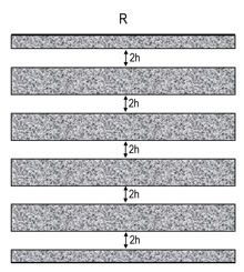 Figure 11 Silencer with symmetrical baffle arrangement |
But this is not the only way to consider boosting the performance of silencers with the SILDIS® software, for a combination of geometric parameters e.g. thickness and spacing of the sound-absorbing coating, silencer length (macro-geometry) being fixed. Indeed, as detailed in another article on this site[6] an asymmetric (alternating) packing, illustrated by the RA'' and RA''' assemblies of figures 12 and 13 - these are schematic longitudinal sections (not taking into account possible variations in the shape of the ends of the baffles at the inlet and outlet of the silencers) - can maximize the attenuation of a silencer in a frequency band of interest.
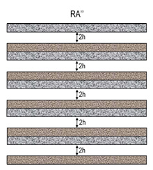 Figure 12 Silencer with asymmetric baffle arrangement, with variation in construction (constant thickness and spacing of baffles) |
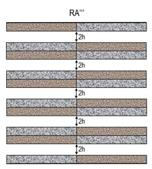 Figure 13 Silencer with asymmetric baffle arrangement, with variation in construction (constant thickness and spacing of baffles) |
This is illustrated by Figures 14 (with a narrow band presentation) and 15 (with a 1/1 octave band presentation). The propagation loss can be significantly increased (in the present case by 5 dB to 15 dB) for the RA''/RA''' arrangement in the 1/1 octave frequency bands centered on 125 Hz and/or 250 Hz by using a different sound absorbing lining for half of the surfaces in contact with the fluid (in the present case: by the addition of a membrane, in other cases possibly by varying the nature of the wool constituting the core of the baffles), while being maintained almost at the level of that of the R arrangement (single sound-absorbing lining) for the lower frequencies; the decrease in performance of the RA''/RA''' assembly compared to the R assembly may only affect frequencies above 500 Hz for which the acoustic performance (at least in the frequency range corresponding to the highest performance) remains high.
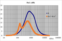 Figure 14 Comparative propagation loss of baffle silencers with single or alternating packing: influence of the constitution |
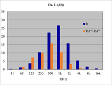 Figure 15 Comparative propagation loss (per octave band) of baffle silencers with single or alternating packing: influence of the constitution |
How to boost silencer performance with SILDIS® software without changing the free passage rate for the fluid or the length of the silencer
A way to boost silencer performance with SILDIS® software, without changing the free passage rate for the fluid, nor the length of the silencer, is to consider an asymmetry based on the thickness of the multi-layer acoustic structure absorbing the sounds (implying, in the case of a silencer with a rectangular section, the non-uniqueness of the thickness of the baffles as illustrated by the RA' assembly in Figure 16).
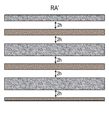 Figure 16 Silencer with asymmetric baffle arrangement, with thickness variation |
For a constant spacing (2h), the conservation of the passage rate only implies an average thickness of the baffles for the RA' assembly equal to that (single) of the baffles of the R assembly.
The equivalence of the total pressure loss for the 2 assemblies does not however result from the equality of the fluid passage rates (depending on the ratio of each baffle thickness to the single air path 2h and the geometry of the upstream and downstream end of the splitters); the use of splitters with a lesser thickness is accompanied by a reduction in the total pressure loss, this better aerodynamic performance constituting one of the major interests of using the asymmetric RA' assembly.
As for the acoustic performance, it is often in no way prohibitive with regard to the use of an asymmetrical baffle arrangement due to the variation in thickness.
Figures 17 (single frequency presentation) and 18 (1/1 octave band presentation) illustrate the propagation loss simulated with the SILDIS® software (for a length of 1 m, and for the same width of the 2h airways):
- one based on R assembly of figure 10 i.e. with a single sound absorbing lining
- the other based on RA' assembly of figure 14 i.e. with sound-absorbing padding alternating with variation in the thickness of the baffles (half with a thickness 2d and half with a thickness 2d.x with x<1)
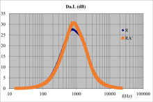 Figure 17 Comparative acoustic performance of baffle silencers with single or alternating packing: influence of thickness |
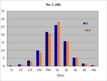 Figure 18 Comparative acoustic performance (by octave band) of baffle silencers with single or alternating packing: influence of thickness |
It emerges - for the considered example - that the difference in terms of propagation loss for the RA' assembly (alternating sound-absorbing lining with variation in thickness), when it is unfavourable (which is not the case at all frequencies), does not exceed 1.1 dB over the entire frequency spectrum (i.e. for the 1/1 octave bands with a central frequency of 31 Hz to 16 kHz) while the calculations show for these configurations a reduction in the total pressure loss (pressure drop) of 18% in favour of the RA' assembly (with a simultaneous reduction in the frontal section of the silencer of 9%) in favour of the RA' assembly.
Of course, different combinations of some input data can induce different variations in comparative performance for the R (symmetrical sound-absorbing lining) and RA' (asymmetrical sound-absorbing lining i.e. alternating with variation in thickness) arrangements, but the trend is always the same: it is with respect to aspects other than acoustic performance (which is more or less maintained) that the competitiveness of a silencer can be increased with an asymmetrical baffle arrangement, with variation in thickness
- size/footprint: it is reduced, at least for the front section of the silencer
- manufacturing cost: it is reduced, at least as regards the quantity of material for the sound absorbing lining of half of the baffles of a rectangular silencer, and for its casing (on two sides)
- aeraulic(aerodynamic) performance: it is improved since the pressure drop (i.e. total pressure loss) is (significantly) reduced
Overall, regarding ways to boost silencer performance with SILDIS® software
Module 1 of the SILDIS® software, for predicting the acoustic and aeraulic (aerodynamic) performance of silencers, allows the consideration of all input data relating to the dimensioning of dissipative (i.e. comprising a sound-absorbing lining) noise attenuators, whether they are with a rectangular section i.e. with baffles or circular i.e. cylindrical (with or without a central pod), well beyond its macro-geometry (thickness and spacing of the sound-absorbing lining, length of the silencer):
- properties and dimensions of all elements of the multi-layer acoustic structure of the sound-absorbing padding, combining porous media, surfacing and perforated protections
- service conditions (nature, thermodynamic conditions and those linked to the flow rate of any fluid) even when very different from those of an air-conditioned aeraulics laboratory
The software output data covers all the needs in terms of acoustic indicators relating to a silencer (calculated for 1/21 octave frequencies from 20 Hz - and even less - to 20 kHz - and even more - or expressed by 1/3 octave or octave band and in overall level with A weighting when it makes sense), first and foremost the propagation loss Da.L (dB), proportional to the length L of the silencer, limited by the bypass paths of the sound waves e.g. longitudinally, at the level of the walls of the silencer envelope - which can be accounted for by a corrective term Dc (dB) - and supplemented by the reflection loss Dr (dB) linked to the change in section upstream and downstream of the splitters (baffles). These quantities are provided separately (as illustrated in figures 19, 20, 21) and in the form of a sum, for what concerns the insertion loss without consideration of the self-noise (flow noise) Di' = Da.L + Dc + Dr (dB) cf. figures 22 and 23 (a table of numerical values is also available for Da.L, Dc, Dr considered separately).
 Figure 19 Propagation loss of a baffle silencer as a function of frequency |
 Figure 20 Bypass correction of a baffle silencer as a function of frequency |
 Figure 21 Reflection loss of a baffle silencer as a function of frequency |
 Figure 22 Insertion loss of a baffle silencer without self-noise i.e. without flow noise as a function of frequency (curve) |
 Figure 23 Insertion loss of a baffle silencer without self-noise i.e. without flow noise as a function of frequency (table) |
The insertion loss without self-noise (i.e. without noise due to the fluid flow) D'i (dB) considered previously can be subtracted from the sound power level without silencer Lw0 (dB ref. 1pW), and the result of this operation Lw1' (dB) can be combined - by means of a "logarithmic summation" - with the self-noise level of the silencer i.e. the sound power level emitted by the fluid flow between the baffles (splitters) Lw (dB ref. 1pW) to obtain the sound power level with silencer Lw1 (dB ref. 1pW); the "dynamic" insertion loss i.e. the insertion loss taking into account the flow noise is then Di = Lw1 - Lw0 (dB) (cf. figures 24 and 25).
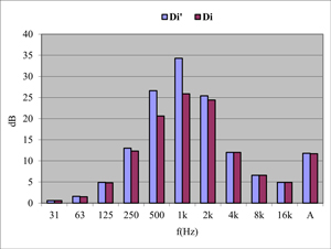 Figure 24 Static and dynamic insertion loss of a baffle silencer |
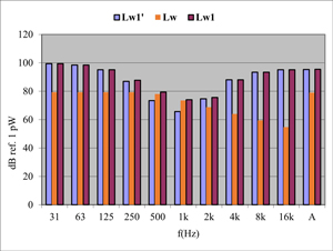 Figure 25 Sound power level reduction of a baffle silencer |
The insertion loss of a baffle silencer taking into account the flow noise Di (dB) as mentioned above (calculated with the SILDIS® software) is comparable to the measurement results according to the standard NF EN ISO 7235 Acoustics - Laboratory measurement procedures for duct silencers and terminal units - Insertion loss, flow noise and total pressure loss (for what concerns the aerodynamic performance, the total pressure loss is calculated by the software).
It should be noted that all these simulation results are obtained using a tool SILDIS®):
- whose development was started by ITS human resource in 1990
- which has been the subject, over time, of a continuous improvement plan regarding its formulations and algorithms and of validations based in particular on the comparison between simulation results and measurements (in laboratories and on-site)
- which now comes in the form of an Excel format program, user-friendly, easy to use[10] and providing instant calculation results, while being reliable and versatile (including libraries of material properties from measurements in certified laboratories)
- whose edition conditions are periodically verified to comply with the requirements of the ISO 9001 standard [11]
The SILDIS® software is based on an analytical approach, which distinguishes it from other commercial tools, which ITS also owns[12] (is the modeling of sound absorbing filling always the best of the best for such simulations CFD/FEM/BEM ??) , with which it is possible (at the end of a tedious learning process, having to spend a lot of time each time modeling the geometry of the silencer - even when it is simple -, and at the cost of time-consuming meshings tasks and calculations) to perform simulations of the performance of silencers, however without the combination of features that make SILDIS® a unique tool.
Thus, SILDIS® software has all the appropriate functionalities for multifactorial assessment of silencer performance, without any known limitation of the combination of parameters or of effects. It can therefore be particularly useful in different contexts:
- sizing (in the context of acoustic engineering missions by more or less specialized firms) of noise attenuators for projects in the building sector or for industrial applications
- development of devices for limiting noise emissions by companies linked to soundproofing equipment fabrication
The possibilities offered to play on all the components of the efficiency of a noise reduction device of an air or pressurized fluid network are a major factor for the finer points of the modelings e.g. in terms of acoustics and aerodynamics, which conditions the selection or development and improvement of soundproofing products with competitive advantages (possibly combined): size, manufacturing cost, aeraulic (aerodynamic) performance, acoustic performance: Icône de validation par la communauté
- the order of appearance of each component in the above enumeration not necessarily reflecting the issues in all contexts
- should just one of these components of a silencer's performance be lacking, the marketing of the incriminated equipment would be problematic (if not its acceptance, assuming that it would be installed despite its weakness)
For a given thickness and width of the airways (i.e. the spacing of the sound-absorbing lining), the optimization with the SILDIS® software of the acoustic structure constituting the dissipative silencer filling both in quality and quantity e.g. selection of porous media, surfacing and protection with the most appropriate characteristics and thicknesses (with regard to which the power of the COALA routine - COmputation of Acoustic LAyers - of the SILDIS® software is decisive for a refined consideration of the properties of each layer and its interactions with neighboring layers), makes it possible to maximize the sound attenuation i.e. the acoustic performance, and when this induces the possibility of a silencer of shorter length, allows the reduction of both the size, the manufacturing cost and the pressure drop - which illustrates an improvement in the aeraulic (aerodynamic) performance -; all the components of the silencer performance are thus favorably impacted.
By modulating the distribution of the quantity of sound-absorbing materials between the surfaces facing on either side of the air passages (i.e. by varying the thickness of the splitters of a silencer), it is possible to determine with the SILDIS® software a minimized total pressure loss - which illustrates an improvement in the aeraulic (aerodynamic) performance - combined with a reduction in both the size and the manufacturing cost, while the variation in acoustic performance can be kept sufficiently low to be acceptable; 3 of the 4 components of the silencer's performance are thus favorably impacted, with a quasi status quo for the fourth.
What has been illustrated above (in terms of the ability to best identify and improve - sometimes through innovative solutions - the sound attenuation and pressure drop of dissipative silencers i.e. with sound absorbing lining) mainly for rectangular cross sections is also valid for circular cross sections i.e. for cylindrical silencers[13].
Anyone is therefore free to consider that SILDIS® software is the ultimate tool for boosting silencer performance, in contexts as varied as the design and construction of noise attenuation devices not only for air networks of Heating Ventilation Air Conditioning - HVAC - facilities, but also for other larger technical facilities (ventilation systems for noisy equipment enclosures, machine rooms, premises for engines and for generator sets, air intakes for compressors and combustion turbines, air inlets and discharges of cooling towers, exhaust ducts and chimneys for burnt gases).
In addition, Module 1B of the SILDIS® software allows the prediction of the acoustic and aeraulic (aerodynamic) performances of reactive silencers, i.e. whose performance is based on changes in section (e.g. by the means of chambers connected with pipes) and direction of the gas flow, thus completing the range of noise attenuation devices for which insertion loss (or sound transmission loss i.e. sound power reduction) and pressure loss can be simulated and optimized in all contexts.
Spread the word !
[0] cf. What are the input data useful for the design of a silencer ?
[1] Sound Impact Limitation Design for Industrial Solutions cf. https://www.its-acoustique.fr/en/acoustical-insulation-soundproofing/acoustic-aeraulic-construction-cad-calculation-software.html
[3] cf. Prediction of acoustic and aerodynamic performance of silencers - software SILDIS® Module 1
[6] cf. Design and calculations of high performance baffle (splitter) silencers
[7] characteristics taken into account: resistivity, porosity, tortuosity, thermal characteristic length, viscous characteristic length, density, thickness
[8] characteristics taken into account: airflow resistance, mass density, thickness
[9] characteristics taken into account: porosity, perforation geometry, mass density, thickness
[11] cf. Quality management
[12] cf. https://www.its-acoustique.fr/en/updates/acoustic-aerodynamic-finite-element-modeling-silencer